
Allen & Heath (click to expand)
Allen & Heath (click to expand)
AHM Protocol documentation:
https://www.allen-heath.com/content/uploads/2023/11/AHM-TCP-Protocol-V1.4.pdf
AHM Control software download:
https://www.allen-heath.com/hardware/ahm/ahm-32/resources/
Find the unit with control software. Under discovery, you will find out if the version is correct. It is important to use a compatible version here to avoid damaging the file.
We can either use group addresses or pure output numbers as addresses. For group addresses, we use the prefix GC before the group number. For example, 'GC1'.
Supported features
Models | Volume (Gain) | Mute/Unmute | Source Select | Meter |
AHM Series | ✅ | ✅ | ✅ |
|
Object address example
Volume (Gain) | Mute/Unmute | Source Select | Meter |
GC1 | N/A | (Input number) | N/A |
Audac (click to expand)
Audac (click to expand)
MTX Commands: https://downloadspvsglobal.azureedge.net/downloads/audac/products/manuals/MTX_Commands_Manual.pdf
M2 Commands:
https://downloadspvsglobal.azureedge.net/downloads/audac/products/manuals/M2_Commands_Manual.pdf
The object addresses are zone numbers 1-8. They will most likely match the zone numbers on the panels, if not, you will need to try different ones to find the correct one.
Supported features
Models | Volume (Gain) | Mute/Unmute | Source Select | Meter |
MTX | ✅ | ✅ | ✅ |
|
M2 | ✅ | ✅ | ✅ |
|
LUNA-F | ✅ | ✅ | ✅ |
|
Object address example
Volume (Gain) | Mute/Unmute | Source Select | Meter |
Zone number (1-8) | N/A | Input number | N/A |
Biamp (click to expand)
Biamp (click to expand)
Designer software: https://support.biamp.com/Tesira/Software-Firmware
The address is the zone name and channel number.
Supported features
Models | Volume (Gain) | Mute/Unmute | Source Select | Meter |
Tesira Series | ✅ | ✅ | ✅ |
|
Nexia Series | ✅ | ✅ | ✅ |
|
Object address example
Volume (Gain) | Mute/Unmute | Source Select | Meter |
zonename:channel | N/A | Source selector name. | N/A |
Bosch (click to expand)
Bosch (click to expand)
Setup
Bosch mixers feature predefined zones and gains, typically including two distinct gains per zone based on observed installations:
A master gain controlling all inputs for each zone.
A dedicated gain specifically for sources within each zone.
Due to this setup, each zone requires configuring a master/slave gain pair to facilitate proper control.
Object Addresses
Object addresses are predetermined and are used for controlling source selection, mute, and gain simultaneously. A distinctive aspect of Bosch DSP systems is that gain, mute, and source selection are set using a single command. Thus, setting the gain automatically sets the source as well, making accurate setup of sources and selectors critical for correct functionality.
Supported features
Models | Volume (Gain) | Mute/Unmute | Source Select | Meter |
Plena Matrix | ✅ | ✅ | ✅ |
|
Object address example
Volume (Gain) | Mute/Unmute | Source Select | Meter |
number | N/A | same number | N/A |
Bose (click to expand)
Bose (click to expand)
Protocol docs:
1. Introduction
Bose DSP systems (ControlSpace) utilize block names as object addresses for controlling gains and source selectors.
2. Object Addresses
Block names serve as addresses for both gains and source selectors. These names typically correspond to display labels indicating the relevant zone. Older versions of ControlSpace Designer allow multiple blocks to share identical names, which will result in errors when reading or setting values. To avoid this issue, ensure all relevant block names are unique within the file.
2.1 Gain
Gain blocks within ControlSpace use their displayed names as addresses:
[Block Name]
2.2 Source Selectors
Source selector blocks in ControlSpace also use their displayed names as addresses:
[Block Name]
2.3 Groups
ControlSpace allows grouping of similar objects, enabling combined control through panels or commands. This grouping feature is particularly beneficial in installations without a DSP, offering better gain management. Group addresses are automatically assigned indices by ControlSpace Designer, thus eliminating the risk of name duplication.
Supported features
Models | Volume (Gain) | Mute/Unmute | Source Select | Meter |
ControlSpace EX-1280C, | ✅ | ✅ | ✅ |
|
ControlSpace EX-1280 | ✅ | ✅ | ✅ |
|
ControlSpace ESP-880, | ✅ | ✅ | ✅ |
|
ControlSpace ESP-00 II, ESP-00, | ✅ | ✅ | ✅ |
|
PowerMatch PM8500N, PM8250N, PM4500N, PM4250N | ✅ | ✅ | ✅ |
|
PowerShare PS404D, PS604D | ✅ | ✅ | ✅ |
|
CSP-480, CSP-1248 | ✅ | ✅ | ✅ |
|
Object address example
Volume (Gain) | Mute/Unmute | Source Select | Meter |
zone name | N/A | name | N/A |
BSS Soundweb London (click to expand)
BSS Soundweb London (click to expand)
1. Introduction
BSS DSP devices utilize object addresses within Audio Architect software for controlling gains, mute states, and source selection.
2. Object Addresses
Object addresses can be identified within Audio Architect by clicking on the relevant block and checking the lower window overview or navigating through the Venue Explorer.
2.1 Gains
Addresses for gains in Audio Architect follow this format:
[ObjectAddress]:[ParameterAddress]
Example of a 4-zone gain-n-input block:
0xA68303000100:0x00000xA68303000100:0x00010xA68303000100:0x00020xA68303000100:0x0003
To verify addresses or find new ones, use Venue Explorer in Audio Architect to locate exact parameter addresses. Single gain blocks typically have parameter address 0x0000.
Note: Older BSS processors configured with London Architect may have different addressing conventions.
2.2 Mute
Mute addresses for gain-n-input blocks typically follow this pattern, using the base address from the gain with an offset starting at 0x0020:
0xA68303000100:0x00200xA68303000100:0x00210xA68303000100:0x00220xA68303000100:0x0023
Single gain blocks have mute addresses set to 0x0001.
Note: Addressing in London Architect systems may differ.
2.3 Source Selector
Audio Architect uses "Source Selector" blocks for selecting input sources. Each selector can feed multiple zones, and its parameter value indicates the active source index.
Example source selector address:
0x000103000113:0x0001
Setup guidelines:
Assign input indexes as the object addresses under HubItem within Waved.
Define object addresses for each zone's source selector; multiple zones can share selectors.
Once configured, the Hub subscribes to source selector values to manage source regulation across different zones.
If input indexes vary between source selectors, a mapping method must be implemented to correlate input indexes to each specific selector.
Supported features
Models | Volume (Gain) | Mute/Unmute | Source Select | Meter |
BLU Series | ✅ | ✅ | ✅ | ✅ |
Object address example
Volume (Gain) | Mute/Unmute | Source Select | Meter |
0xA68303000100:0x0000 | 0xA68303000100:0x0020 | 0x000102000006:0x0000 | N/A |
Cloud (click to expand)
Cloud (click to expand)
Cloud protocol docs:
https://www.cloud.co.uk/public-download/Q1YgQW1wbGlmaWVyIFNlcmlhbCBDb250cm9sIFByb3RvY29sIFYxLjAucGRm/ZmlsZXMvLzk5NGQ5MWNlNWU1N2FjNGY5NmQ5ZjczZmI0NTMxNjM3LnBkZg–
The Cloud network discovery tool is used to find the processor on the network. With this tool, you can view and change the IP address. You can also double-click the device to open a web app used for configuration. The default PIN code is: 1234
Supported features
Models | Volume (Gain) | Mute/Unmute | Source Select | Meter |
Known Digital | ✅ | ✅ | ✅ |
|
dbx ZonePRO (click to expand)
dbx ZonePRO (click to expand)
The dbx ZonePRO can be controlled via Ethernet or RS-232.
Useful resources:
Product Details: [Link to product page]
Protocol Documentation: [Link to documentation]
Control Software: [Link to control software]
Note: The provided documentation references RS-232 communication, but the same guidelines apply for Ethernet control (refer to the Appendix section in the original documentation).
2. Object Addresses
Object addressing in ZonePRO can initially appear complex. Addresses are identified using the ZonePRO GUI Designer software. For the 641m model, the GUI appears as follows:
Highlighted elements within the GUI correspond to the objects that control volume and input source. To inspect these objects, double-click on the respective GUI elements.
To find an object's address, first select the zone within the GUI, then press:
Ctrl + Shift + O
This action will reveal the bytes: b0, b1, b2, b3.
3. Constructing Object Addresses
Object addresses for use within the Waved app are constructed as follows:
0x [(Node ID in 2-byte hexadecimal, LSB-first), b0, b1, b2, b3]
Example:
Node ID: 186
b0, b1, b2, b3: 20, 2, 5, 1
The resulting object address becomes:
0xBA0016020501
Ensure correct entry to avoid communication issues.
Supported features
Models | Volume (Gain) | Mute/Unmute | Source Select | Meter |
ZoneProSeries | ✅ | ✅ | ✅ |
|
Genelec (click to expand)
Genelec (click to expand)
When you add a Genelec processor in the Waved installation view a new tab "Speakers" will appear.
Click "Add speakers".
When the speakers appear you can use "Blink" or "Mute" to identify the speakers and place them in the designated zone.

Supported features
Models | Volume (Gain) | Mute/Unmute | Source Select | Meter |
Smart IP | ✅ | ✅ | ✅ |
|
K-Array (click to expand)
K-Array (click to expand)
On the K-Array integration object addresses simply refer to either input number or output number, both integers in the range 1-4, 1-8 or 1-16 depending on the dsp size.
Sources
K-Array supports matrix source selectors and not normal source selectors
When creating a Matrix Source Selector the Output number must be the same as the Object Address of the zone it will control. By extension this means that each zone must have its dedicated source selector.
Supported features
Models | Volume (Gain) | Mute/Unmute | Source Select | Meter |
Kommander | ✅ | ✅ | ✅ |
|
Qsys/QSC (click to expand)
Qsys/QSC (click to expand)
Useful resources:
QRC Documentation: https://q-syshelp.qsc.com/Content/External_Control_APIs/QRC/QRC_Commands.htm
Designer Software: https://www.qsc.com/resources/software-and-firmware/q-sys-designer-software
Designer Software
In Q-Sys Designer software, you can retrieve existing files from the network by selecting:
File > Load from Core and Connect
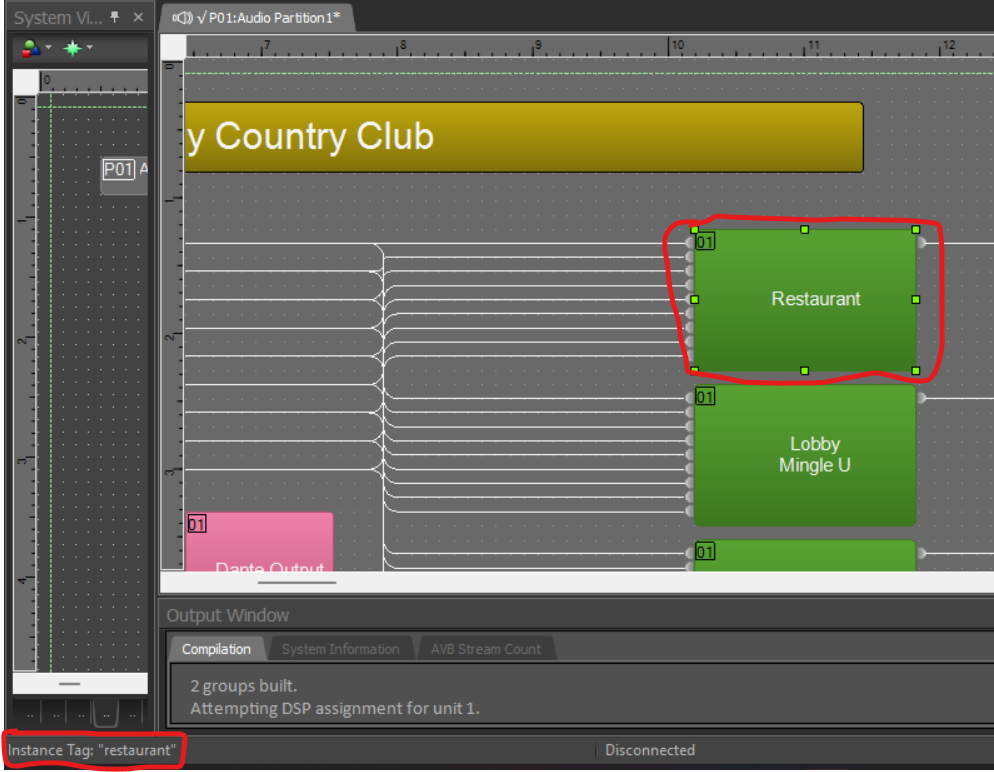
Within this file, gain blocks can be used for volume control.
Object Addresses
Gains
Object addresses are derived from the names of the blocks you wish to control. In recent versions of Q-Sys Designer, labels alone are insufficient—you must set or read the "Code Name" from the right-hand column:
In older software versions, simply naming the block is enough.
Matrix Blocks
In some scenarios, volume control is done using a 1x1 Matrix block. In such cases, the syntax used for addresses is slightly different, using:
MX:<displayName>
For example, to control output gain:
MX:Lounge orange
Minimum and Maximum Values
The default range for gain in Q-Sys Designer is -100 dB to +20 dB. These can be customized, potentially limiting slider functionality. Special attention is required when controlling the master volume, as discrepancies between the app and real values could lead to endless compensation loops. A fix will be introduced if this becomes a frequent issue.
Source Selector / Router
Q-Sys Designer uses "Router" instead of "Source Selector," though they function similarly despite appearing as a matrix visually.
Addresses follow this format:
<displayName>:<outputNumber>
For example, channel 1 of a router would have the following object address:
routeren:1
Supported features
Models | Volume (Gain) | Mute/Unmute | Source Select | Meter |
Core | ✅ | ✅ | ✅ |
|
Sonos (click to expand)
Sonos (click to expand)
When you add a Sonos processor in the Waved installation view a new tab (Speakers) will appear.
Click "Add speakers".
When the speakers appear you can use "Blink" or "Mute" to identify the speakers and place them in the designated zone.
Supported features
Models | Volume (Gain) | Mute/Unmute | Source Select | Meter |
All known | ✅ | ✅ |
|
|
Stoltzen (click to expand)
Stoltzen (click to expand)
The Stoltzen Typhoon X88 DSP can be controlled and configured using the Flow software, accessible directly from the device through a web interface.
Useful resources:
Protocol Documentation: View Protocol Docs
Product Information and User Guide: Stoltzen Typhoon X88 DSP
Default IP Address: 169.254.10.227
Subnet Mask: 255.255.0.0
2. Setup
Flow Software Interface
To connect to a device:
Ensure your computer is on the same subnet as the device.
Open the Flow software and click Device List in the upper-right corner.
Select the device from the list and click Connect.
IP addresses can also be set from this interface.
3. Object Addresses
Output Addresses
Addresses correspond to output numbers on the processor, starting at 0.
Grouping Outputs
Outputs can be grouped using the following format:
G:1,2,3
This example groups outputs 1, 2, and 3 into one zone.
Source Selection
Currently, only source selection via matrix on the input row is supported for Stoltzen DSP.
Define a source matrix with the object address
matrix.Use exactly one source selector configured with output number 1.
This configuration specifically addresses needs like those at Paleet, where external wall panels are not used. This allows the integration to use sourcematrixsubscribe, reducing unnecessary polling and network requests.
Supported features
Models | Volume (Gain) | Mute/Unmute | Source Select | Meter |
TyphoonSeries | ✅ | ✅ | ✅ |
|
Symetrix (click to expand)
Symetrix (click to expand)
1. Introduction
Symetrix DSPs use two distinct protocols, Composer Control Protocol and Jupiter Protocol, depending on the DSP model:
Composer DSP
Protocol Documentation: Composer Control Protocol v7.0
Designer Software: Symetrix Composer Software
TCP/IP Port: 48631
Note: The IP address can be found using the connection wizard in Composer software or via the front panel of the DSP.
Jupiter DSP
Protocol Documentation: Jupiter Control Protocol
Designer Software: Symetrix Jupiter Software
UDP Port: 48630
2. Setup
Composer DSP
To extract the configuration file from the DSP using Composer:
Open Composer software.
Navigate to:
Hardware > Locate Hardware
Select your device from the list.
Click:
Go online (Pull site file from hardware)
Jupiter DSP
Jupiter software uses a different approach. Control elements are associated with pre-assigned Controller Numbers:
Retrieve Controller Numbers through the Custom Preset Parameter Browser in the Jupiter software.
The Controller Numbers appear in the lower-right column of the software interface.
3. Object Addresses
Composer DSP
The Remote Control Manager displays all controls assigned to external panels:
Right-click on any block in Composer software.
Select Remote Control Manager to view the control numbers.
Source Selection
Source-selector blocks within Composer software use similar object addresses as volume controls. Addresses correspond directly to their assigned source indices.
Jupiter DSP
Object addresses (Controller Numbers) for Jupiter DSPs can be found via:
Custom Preset Parameter Browser within Jupiter software.
Match control names with corresponding Controller Numbers from the displayed list to correctly address the DSP.
Example: If a Symetrix panel is present, identify the targeted control element in the software to obtain the correct Controller Number.
Supported features
Models | Volume (Gain) | Mute/Unmute | Source Select | Meter |
Edge | ✅ | ✅ | ✅ |
|
Radius | ✅ | ✅ | ✅ |
|
Prism | ✅ | ✅ | ✅ |
|
Solus NX | ✅ | ✅ | ✅ |
|
Jupiter | ✅ | ✅ | ✅ |
|
Xilica (click to expand)
Xilica (click to expand)
1. Introduction
Xilica DSPs use a TCP/IP protocol operating on port 10007.
Useful Resources:
Current Protocol Documentation: Xilica Solaro Third Party Guide
Legacy Documentation: Third Party Control Protocol
Xilica Designer Software: Download Xilica Designer
Important: Xilica’s protocol requires manually naming the objects (gain, mute, source selectors) in the Designer software, meaning configuration updates are often required during installation.
2. Setup
To discover Xilica devices on a network:
Open the Xilica Designer software.
Select Network View.
Devices can be discovered even when not on the same subnet, although accessing device files requires subnet alignment.
Configuration can be accessed live through Network View for real-time adjustments or saved locally and viewed in Project View.
3. Object Addresses
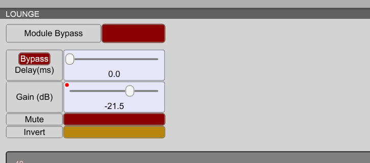
3.1 Gain
Xilica requires manually naming parameters to be controlled externally:
Double-click the desired gain block (e.g., LOUNGE).
Hold Ctrl, right-click the slider container, then select:
Add/Change 3rd Party Control Object Name
To review assigned object names:
Navigate to Project > Device 3rd Party Control Elements in the main menu.
After assigning names to all parameters, upload the updated configuration:
Click Load Design to Device(s).
3.2 Mute
Mute parameters must be defined separately as they are dedicated components:
Assign and manage mute addresses similarly to gain objects.
3.3 Source Selectors
Source selection in Xilica uses a component called "Input Selector":
Assign object addresses as you would with gain objects.
3.3.1 Matrix-Based Source Selection
Matrix-based source selection is currently unsupported in Xilica. The recommended workaround is to replace matrices with input selectors in your design file.
See this video guide for panel-based setup instructions.
As Xilica Designer software cannot link parameters internally, stereo signals with input selectors require manual address linking within the Waved app. Please refer to the dedicated section in the installation guide for detailed instructions on parameter linking.
Supported features
Models | Volume (Gain) | Mute/Unmute | Source Select | Meter |
Solaro | ✅ | ✅ | ✅ |
|
Yamaha (click to expand)
Yamaha (click to expand)
1. Introduction
Yamaha MTX and MRX DSP devices can be controlled using Yamaha’s Remote Control Protocol via Ethernet or serial connection. Communication with the processor occurs through TCP/IP on port 49280.
Useful Resources:
Remote Control Protocol: Yamaha Remote Control Protocol Specification
MRX-MTX Editor Software: Download MRX-MTX Editor
MRX7-D User Manual: Download MRX7-D Manual
2. Setup
Setup and configuration are done through the MTX-MRX Editor software:
Connect the MTX device to a network switch via Ethernet.
Set your PC's static IP to 192.168.0.253.
Open MTX-MRX Editor and create a new project using the configuration wizard.
Deploy the project to the device by going online.
Real-time control of parameters is accessible through the System tab.
2.1 IP Address Configuration
On the rear of the MTX/MRX device, DIP switch number 6 selects how IP addresses are determined:
Unit ID (DIP switch setting): IP set via rotary wheel (e.g., wheel position 2 gives IP 192.168.0.2).
PC (DIP switch setting): IP configured via MTX-MRX Editor at System > Device Information. Ensure PC and device share the same subnet.
2.2 Changing Unit ID
To change the unit ID on an already synchronized DSP:
Retrieve current device configuration via MTX-MRX Editor.
Modify the unit ID in the saved configuration and re-save.
Adjust the rotary wheel to match the new unit ID, power-cycle the DSP, then synchronize by going online.
Ensure no alerts are displayed on the DSP and verify panel functionality.
3. Object Addresses
3.1 MTX Family
Addresses follow this format:
MTX:mem_MemNo/UniqueId/ElmNo/Xpos/Ypos/PrmNo/IndexNo
Example addresses:
MTX-3D:
MTX:mem_512/20024/0/0/0/0/0(Zone index 0)MTX:mem_512/20024/0/1/0/0/0(Zone index 1)
MTX-5D:
MTX:mem_512/20024/0/6/0/0/0MTX:mem_512/20024/0/7/0/0/0MTX:mem_512/60000/2/0/0/0/0(Master volume)
Yamaha MTX devices use general subscriptions rather than individual parameter subscriptions. Use terminal debugging in WavedHub to identify exact addresses by observing parameter changes.
3.2 MRX-7D
The MRX-7D utilizes a designer-file system, allowing the selection of specific parameters for remote control:
Open MTX-MRX Editor, navigate to the Device tab, and select Open MRX Designer.
In MRX Designer, open Tools > Remote Control Setup List.
Drag desired parameters into the remote control list.
Save and upload the file back to the device through MTX-MRX Editor by going online and choosing to device.
Object addresses for MRX-7D follow a simpler format:
MTX:Index_X
Xrepresents the parameter’s number in the remote control setup list.
Supported features
Models | Volume (Gain) | Mute/Unmute | Source Select | Meter |
MTX Series | ✅ | ✅ | ✅ |
|
WavedBox (Analog to digital converter) (click to expand)
WavedBox (Analog to digital converter) (click to expand)
The WavedBox can be used to connect between a mixer and an amplifier to be able to automatically adjust volume on analog systems. You can also connect the source directly to the WavedBox. We recommend using balanced cables.
When the WavedBox is connected to the hub click "add processor" and select "Waved Box" type. You can check the box that automatically adds the three sources (balanced, RCA 1 and RCA 2) and the 6 zones (output 1-6).
Supported features
Models | Volume (Gain) | Mute/Unmute | Source Select | Meter |
WavedBox | ✅ | ✅ | ✅ |
|